The Building Blocks of CPUs: Understanding Instruction Set Architecture
How ISA Bridges Software and Hardware in Modern Processors
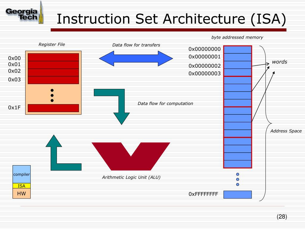
ISA defines the set of instructions that a processor can execute. It provides a functional description of operations, data types, registers, addressing modes, memory organization, and I/O interfaces. Essentially, ISA is the interface between the software and hardware, determining how software interacts with the CPU.
Types of Instruction Set Architectures:
Complex Instruction Set Computing (CISC):
CISC architectures have a large set of instructions, some of which perform complex operations. The goal of CISC is to reduce the number of instructions per program, allowing complex tasks to be performed with fewer lines of code.
Fewer instructions mean reduced memory usage. Higher-level language constructs can be directly implemented in hardware.
It uses less registers and have more addressing modes
The complexity of instructions can lead to slower execution and increased power consumption.
Pipelining is difficult
Example is Intel’s x86 CPUs.
Reduced Instruction Set Computing (RISC):
RISC architectures focus on a smaller set of instructions, with each instruction performing a simple operation. RISC systems emphasize speed by executing instructions in a single clock cycle.
Simplified instructions lead to faster execution. RISC processors are more energy-efficient.
Requires more instructions per program, which may increase memory usage.
It uses more registers and have complexity in compiler
Example is RISC-V.
Very Long Instruction Word (VLIW):
In VLIW, software(compiler) packs independent instructions in a larger instruction bundle to be fetched and executed concurrently.
Packed instrcutions can be logically unrelated.
Compiler finds independent instructions and statically schedule(pack) them in a single VLIW instruction
High parallelism leads to improved performance.
Requires sophisticated compilers and is sensitive to the order of instructions.
It should have following properties
Multiple functional units
All instructions in a bundle are executed in lock step
Instructions in a bundle statically aligned to be directly fed into functional units.
Lock Step Execution: If any operation in VLIW stalls, all instructions stall
Explicitly Parallel Instruction Computing (EPIC):
EPIC architectures, like Intel's Itanium, extend VLIW by explicitly specifying parallel execution opportunities. The compiler plays a significant role in identifying parallelism.
Enhances parallelism and performance.
Complex compilers and hardware design.
Accumulator-Based Architecture:
In this architecture, most operations involve a single, dedicated register called the accumulator.
Simple design and easy to implement.
Limited by the single accumulator, leading to less flexibility.
Instruction Cycle:
The instruction cycle is the process by which a computer retrieves, decodes, and executes an instruction. It consists of several stages:
Fetch: Fetch phase obtains instruction from memory and loads it into instruction register(IR).
It is a 3 step process:
Step-1: Load Memory Access Register(MAR) with contents of PC and simultaneously increament PC.
Step-2: Interrogate memory and place results in Memory Data Register(MDR)
Step-3: Load IR with content of MDR
Decode: The control unit decodes the fetched instruction to determine the operation to be performed and identifies the operands involved.
Evaluate Address: It computes the address of memory instrcution that is needed to process instruction if needed.
Fetch Operands: It obtains the operands needed to process the instrcution.
Execute: The CPU performs the operation specified by the instruction, using the ALU for arithmetic or logical operations, or transferring data between memory and registers.
Write Back: The result of the operation is written back to a register or memory, completing the instruction cycle.
Increment PC: The program counter is updated to point to the next instruction.
Types of Instructions:
Data Transfer Instructions:
MOV,LOAD,STOREThese instructions transfer data between registers, memory, and I/O devices. For example,
MOV A, Bmoves data from register B to register A.
Arithmetic Instructions:
ADD,SUB,MUL,DIVThese instructions perform arithmetic operations like addition, subtraction, multiplication, and division on data.
Logical Instructions:
AND,OR,XOR,NOTThese instructions perform logical operations, manipulating individual bits of data.
Control Flow Instructions:
JMP,CALL,RET,BRANCHControl flow instructions alter the sequence of execution by jumping to different parts of the program or calling subroutines.
Comparison Instructions:
CMP,TESTThese instructions compare values and set flags based on the result, which can influence the flow of control.
Shift and Rotate Instructions:
SHL,SHR,ROL,RORThese instructions shift or rotate bits in a register to the left or right, which is useful for bitwise manipulation and arithmetic.
Input/Output Instructions:
IN,OUTThese instructions handle communication between the CPU and peripheral devices by reading data from input ports and sending data to output ports.
Special Instructions:
NOP,HLTNOPdoes nothing but increments the PC, useful for timing delays.HLThalts the CPU, stopping all operations.
Addressing Modes:
Immediate Addressing:
The operand is specified directly within the instruction.
No memory reference is required to fetch data. So no additional calculations are required to work out the effective address
Register Addressing:
In register addressing the operand is placed in one of 8 bit or 16 bit general purpose registers. The data is in the register that is specified by the instruction.
Direct Addressing:
The operand's address is specified in the instruction.
Only a single memory reference is required to access data. So no additional calculations are required to work out the effective address.
Indirect Addressing:
In Indirect addressing mode, the address field in the instruction contains the memory location or register where the effective address of the operand is present. It requires two memory access.
Indexed Addressing:
The operand's address is determined by adding an index to a base address.
Connect with Me:
LinkedIn: Rana Umar Nadeem
Medium: @ranaumarnadeem
GitHub: ranaumarnadeem/HDL
Substack: We Talk Chips
Tags: #DigitalLogic #CombinationalLogic #Adders #Decoders #Encoders #Mux #Demux #Subtractors #Multipliers #Verilog #HDL #DigitalDesign #FPGA #ComputerEngineering #TechLearning #Electronics #ASIC #RTL #Intel #AMD #Nvidia#substack #github #DFT #DLD #Digital logic#sequential logic #medium #moorelaw #FSM #Von_neumann #harvard #fetch #ISA #RISCV#x86 #Intel #fetch #decode#Pc#store


