

Digital Logic Blocks: Combinational Logic
The Core of Digital Logic: Understanding Combinational Circuits

Combinatioanl logic is the backbone of digital logic. Combinational logic blocks are time independent . There output is solely based on the current inputs. These are also sometimes reffered as decision elements
Let’s delve into the key components of combinational logic.
1. Adders: Adders are fundamental in performing arithmetic operations. They come in two primary types: half adders and full adders. A half adder adds two single-bit binary numbers and produces a sum and a carry. A full adder, on the other hand, adds three bits (two significant bits and a carry bit), allowing for the addition of multi-bit binary numbers. Additionally, advanced adder designs like Ripple Carry Adders and Carry Look-Ahead Adders are used to enhance speed and efficiency.
See detailed post :
Adders and its Types

Adders are fundamental components in digital electronics and are crucial for performing arithmetic operations. In digital systems, adders are used to perform the addition of binary numbers. There are two basic types of adders: Half Adders and Full Adders
2. Decoders: A decoder is a combinational circuit that converts binary information from the 'n' coded inputs to a maximum of 2^n unique outputs. They are often used in memory address decoding, where they select a specific memory location based on the input address.
A decoder has this property that exactly one of its output is 1 and all other are zero.The output that is 1(high) is called one-hot. The one output which is 1 is the output corresponding to the input pattern that is is expected to detect.
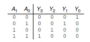
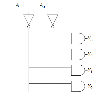
For example A simple decoder with 2 input lines and 4 output lines. Each output line represents one of the possible 2^2 = 4 combinations of the input lines.
Inputs: A, B
Outputs: Y0, Y1, Y2, Y3
The truth table and the diagram is given below
Decoders are widely used in 7-segment display they takr control signals as input and turns on numerical displays. In CPUs, instruction decoders interpret binary-coded instructions and generate control signals to execute them.
3. Encoders: Encoders perform the reverse operation of decoders. They take 2^n input lines and convert them into an 'n' bit binary code. Encoders are commonly used in applications where multiple input lines need to be reduced to a simpler binary code for further processing such as keyboard encoding, decimal to binary converters etc. For example in decoder we had 2 inputs and 4 outputs but in encoder we will have 4 binary inputs and 2 outputs. We assume that only one of the input is 1(High) at a time and all other are false.


4. Multiplexers (Mux): A multiplexer, or Mux, is a device that selects one of several input signals and forwards the selected input to a single output line. Multiplexers are extensively used in data routing, where multiple data sources need to be directed through a single communication line.In gemeral a mux contains 2^n inputs and n select lines.
For example a 4 to 1 multiplexer has four data inputs and one output, as shown in. Two select signals are needed to choose among the four data inputs. The 4:1 multiplexer can be built using sum-of-products logic,tristates, or multiple 2:1 multiplexers. The product terms enabling the tristates can be formed using AND gates and inverters.
See verilog implementation: 4 to 1 MUX


5. Demultiplexers (Demux): A demultiplexer is the opposite of a multiplexer. It takes a single input signal and selects one of many data-output lines, which is then routed to the single input.The operation of a demux involves directing the input signal to one specific output, determined by the binary value of the select lines, while the remaining outputs are set to a default state, usually logic 0. For example, in a 1-to-4 demux, there is one input and four outputs. By changing the values on the two select lines, the input signal can be routed to one of the four outputs, with the other three outputs being inactive. Demux is essential in applications where a single data source needs to be distributed to multiple destinations.
6. Subtractors: Subtractors, like adders, are used in arithmetic operations but for subtraction. They are not as straightforward as adders are let us see how suntraction occurs in hardware.
In binary subtraction, we subtract each bit of one binary number from the corresponding bit of another binary number, starting from the LSB (rightmost bit) and moving towards the MSB (leftmost bit). The basic operations involved are:
Difference Calculation: The difference between two binary digits is calculated using the XOR (exclusive OR) operation. The XOR operation yields a
1if the inputs are different and a0if they are the same.Borrow Calculation: If the minuend (the number from which you are subtracting) is smaller than the subtrahend (the number you are subtracting), a borrow is required. The borrow is calculated using the AND operation and is propagated to the next higher bit.
In simple words to calculate Output= A-B. We first create 2’s complement of B and then simply add A and Comp(B).
Subtractors further have two types
A Half Subtractor is designed to handle the subtraction of two single-bit binary numbers. It has two inputs: the minuend (the number from which another number is to be subtracted) and the subtrahend (the number to be subtracted). The Half Subtractor produces two outputs: the difference and the borrow. The logic equations governing a Half Subtractor are:
Difference (D) = A ⊕ B (XOR operation)
Borrow (B) = A' ∧ B (AND operation with A negated)
This type of subtractor is suitable only for subtracting the least significant bit (LSB) in multi-bit operations, as it does not account for a borrow-in from previous bits.
A Full Subtractor is capable of handling the subtraction of binary numbers with a borrow-in. It extends the functionality of the Half Subtractor by including an additional input for the borrow from the previous stage. This allows it to subtract three bits: the minuend, the subtrahend, and the borrow-in. The Full Subtractor produces two outputs: the difference and the borrow-out. The logic equations for a Full Subtractor are:
Difference (D) = A ⊕ B ⊕ Bin
Borrow-out (Bout) = (A' ∧ B) ∨ (Bin ∧ (A ⊕ B))
The Full Subtractor's ability to handle an incoming borrow makes it suitable for multi-bit subtraction operations, where each bit is processed sequentially, and the borrow is propagated through the series of subtractors.
In multi-bit subtraction, multiple Full Subtractors are cascaded to form a larger subtractor capable of handling the entire binary number. Each Full Subtractor processes one bit of the input numbers and passes the borrow to the next stage.
Verilog code for adder-subtractor circuit: Adder-Subtractor
7. Multipliers: Multipliers perform binary multiplication of two binary numbers. Various techniques like array multiplication, Booth’s algorithm, and Wallace Tree multiplication are employed to improve efficiency and speed. Multipliers are integral in digital signal processing and various computational tasks.
Check the post below for details
Multipliers in Digital Logic
A binary multiplier is a digital circuit used to multiply two binary numbers. It takes two binary inputs and produces a binary output that represents the product of the inputs. Binary multiplication involves a series of addition and shift operations, similar to how multiplication is performed manually.
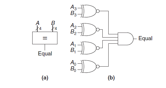
8. Comparators: A comparator determines whether two binary numbers are equal or if one is greater or less than the other. A comparator receives two N-bit binary numbers A and B.
It further has 2 types
Equality comparator
Consider 2 numbers A and B this comparator will simpy tell us that weather A==B.
The equality comparator is the simpler piece of hardware. It first checks to determine whether the corresponding bits in each column of A and B are equal using XNOR gates. The numbers are equal if all of the columns are equal.
An equality comparator compares two binary numbers bit by bit. For two n-bit numbers, the comparator checks each corresponding pair of bits. If all pairs are equal, the comparator outputs a signal indicating equality; otherwise, it outputs a signal indicating inequality.The logic design of an equality comparator involves using basic logic gates (AND, OR, NOT, and XOR) to perform the comparison. Let's break down the design for a simple 1-bit comparator and then extend it to a multi-bit comparator.

Magnitude Comparator
A magnitude comparator is a digital logic circuit that compares the magnitudes of two binary numbers and checks weather they are equal are not.
A magnitude comparator takes two binary numbers as inputs and produces three outputs, each indicating one of the following conditions:
A > B: Output is high if the first number (A) is greater than the second number (B).
A < B: Output is high if the first number (A) is less than the second number (B).
A = B: Output is high if both numbers are equal.
If the two corresponding bits are equal, the circuit moves to the next bit position and compares the next pair of bits. This process continues until all the bits have been compared. If at any point in the comparison, the circuit determines that the first number is greater or less than the second number, the comparison is terminated, and the appropriate output is generated.
Connect with Me:
GitHub: ranaumarnadeem/HDL
Medium: @ranaumarnadeem
Substack: We Talk Chips
LinkedIn: Rana Umar Nadeem
Tags: #DigitalLogic #CombinationalLogic #Adders #Decoders #Encoders #Mux #Demux #Subtractors #Multipliers #Verilog #HDL #DigitalDesign #FPGA #ComputerEngineering #TechLearning #Electronics #ASIC #RTL #Intel #AMD #Nvidia#substack #github #DFT #DLD #Digital logic